Creating a good contact ratio in a helical gear and worm gear is not always easy.
It is for this reason that I would like to dedicate today’s post – which I wrote with Luca Barbieri, head of the research and development department of MICROingranaggi, to this topic.
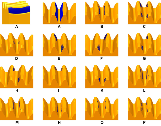
I will start by saying that, before commencing the production of a batch, it is advisable to check the gear on the bench, positioning the two components – helical gear and worm – at the operation center distance and “dirtying” the worm with ink (excellent good old Prussian blue). In this way turning the pair, the colour will end up on the tooth of the wheel in the contact zone. It is at this point that we often realise that contact prints may not be optimal and there may be a variety of causes (see figure); let’s summarise them briefly.
In the meantime, it must be said that a complete contact zone (as in the case of Figure A) can only be achieved theoretically. For this purpose, the hob and the worm gear should be perfectly identical in teeth flank, and pitch diameter. But not only this. In order to obtain a contact zone with these characteristics on the finished gear and mounted on the gearbox for which it is intended, a perfect assembly should also be performed.
Beware though:
it is interesting to know, in fact, that a contact zone with those characteristics should not however be pursued because if it extended to the end of the teeth, there would not be – between the teeth flank – the lubricant necessary to ensure good functioning of the transmission itself.
At the moment of their entry against the teeth flank of the worm, in fact, the edges of the teeth “would scrape” the lubricant. Not to mention that – during assembly – even the slightest error could result in edge contacts.
Conversely,
if the contact area were of a smaller width, a gap would be created that would become gradually wider in the direction of the crown teeth, thus causing the formation of a lubricant gap.
The ideal situation would therefore be to obtain a slightly convex contact area (as in figure B) in terms of the height and width of the tooth.
In general, however, a number of different cases can occur. Let’s look at them in detail.
A contact zone interrupted at the centre and displaced at the two ends (as in figure C) is obtained when the hob has a smaller diameter, and therefore a higher elix angle respect to the worm.
An area of contact that is not very large and located in the centre of the teeth (see figure D) is obtained when the diameter of the hob is considerably higher than that of the worm. In this case the contact area on the worm flank is smaller and, therefore, the ratio contact of the toothing will be less.
When the pitch or angle of inclination of the worm helix is excessive, a contact zone is obtained such as those shown in figures E and F.
Conversely when the pitch or angle of inclination of the worm elix is too low, the contact area will be represented by the figures G and H.
And again: a situation similar to the one I depicted in the images I and K will be obtained when the position of the worm in the direction of helical gear axis is different from that which the hob had during the processing.
Finally, contact areas such as those indicated in the other figures are rarer and are essentially due to camber errors, lead angles or hob sharpening.


