When discussing gear manufacturing errors, the first aspects that usually come to mind are dimensions—diameter, module and dimensional tolerances. These are generally where attention is focused.
However, when dealing with small or miniature gears, this perspective is only part of the picture. Based on our experience,
the most critical errors are rarely dimensional; they are almost always related to the actual geometry of the tooth and its position in space.
The reason is quite straightforward. Within certain limits, a slightly out-of-tolerance diameter can often be accommodated by the backlash between mating gears. Geometric errors, on the other hand, cannot. If the tooth profile or its position is incorrect, the contact between mating teeth becomes uneven, leading to vibration, increased noise and localized wear.
The four types of errors that typically have the greatest impact are:
Runout, namely the cyclic deviation of the gear relative to its axis of rotation.
Profile errors, where the involute tooth profile deviates from its theoretical geometry.
Helix errors, where the tooth is not properly aligned with the gear axis or does not conform to the specified helix geometry.
Pitch errors, where the teeth are not equally spaced around the gear.
In all four cases, these defects directly affect the quality of tooth contact and, most importantly, they cannot be compensated for during operation.
There is another aspect that is less intuitive but equally important: scale.
An error that would be considered negligible on a larger gear may become the dominant factor in a micro gear, simply because a few micrometres represent a significant proportion of the tooth geometry.
This completely changes the engineering perspective. In micro gears, even extremely small geometric deviations can immediately affect operating performance. Tooth contact becomes irregular, noise and vibration increase, and wear tends to concentrate in localized areas.
This is why measurements alone do not always reflect actual operating behaviour. A gear that fully complies with its drawing may still perform poorly in service, while another that appears less than perfect may operate satisfactorily.
From a manufacturing standpoint, this has direct implications for the inspection strategy.
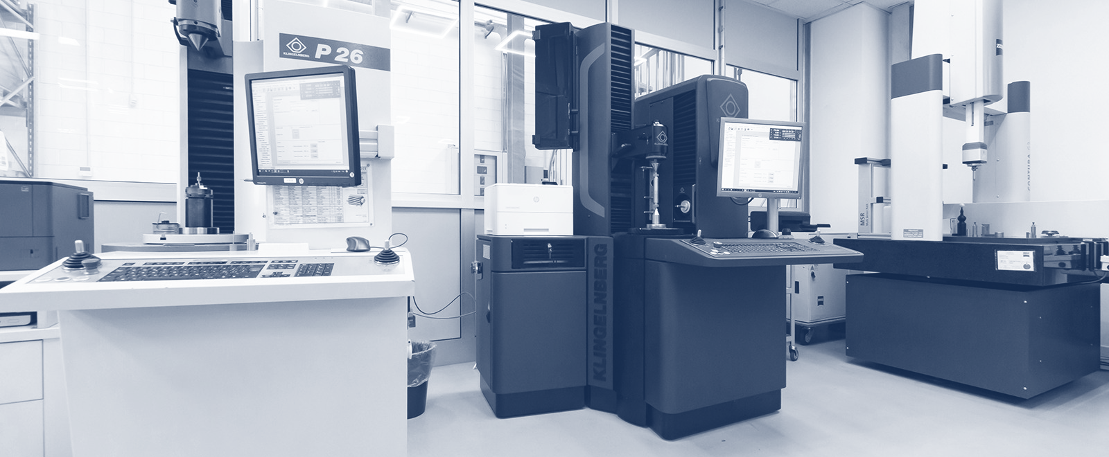
During process development or machine setup, a complete analytical inspection of the gear teeth—for example using a gear measuring machine capable of evaluating involute profile, helix and pitch—is essential. It is the only way to understand how the manufacturing process is actually performing.
Once the process has demonstrated consistent stability, the inspection strategy can change. Faster and more indirect verification methods—such as runout measurements or functional inspections—can then be adopted to reduce inspection time and cost while maintaining effective quality control.
However, this is always a compromise, and it should only be adopted when the manufacturing process has proven to be genuinely stable.
Process stability is never something that can simply be assumed. It must be demonstrated over time by monitoring indicators such as scrap rate trends, measurement variation and statistical capability indices such as Cp and Cpk, which indicate how consistently the process remains within the specified tolerances.